Monday, December 17, 2018

A (Not So) Minor Rewrite

I've written recently about shortcomings in my map generation caused by using Voronoi cells/Delauney triangles to define land masses.  One problem I noted when implementing barrier islands -- because land must be at least one Delauney triangle in size, barrier islands could only be made so thin.  And even with a high density of triangles, the resulting islands would be very jagged because the coastline followed the triangle edges:
Another problem was that I couldn't generate a coastline with the kind of fractal detail that you often see in maps drawn by people.  And if I did add a lot of jagged detail to the coastline, it no longer followed the land exactly, resulting in the land or the sea showing through where it shouldn't:
Here you can see spots where the land sticks out a bit past the border.

The solution to this problem is to define land (at least when drawing the map) by the space enclosed by the coastline.  This is a pretty significant change -- I rely quite heavily on the underlying grid of Delauney triangles to draw the map.  For example, I consult locations to determine the biomes, colors, and other features that should be displayed there on the map.  But using actual polygons to define land masses (even if I continue to use the underlying grid for other purposes) would bring significant benefits, so I decided to at least explore the feasibility.

(Much of the initial work for this I did on an Amtrak train ride to New Jersey, and I wasn't able to capture screenshots, so this first part will be somewhat dry.)

To begin with, I kept world generation unchanged, but as a final step I captured all the coastlines as polygons and saved them.  Initially, some of these coastlines did not form closed loops since I have avoided creating coastlines around the very edge of the map.  In the past, coastlines at the very edge of the map caused some difficulties, so I simply did not generate coastlines in those areas.  However, my work setting DA up to generate continent-sized maps removed those issues, so I was now able to modify the generation of coastlines to only create closed loops.  So now the map generates all land masses as closed-loop polygons without any holes.

Here's an example of my current approach.  The coastline follows the edges of the triangles, so each triangle falls either completely in the land or completely in the sea.  A red dot marks the center of every location that has a height greater than zero, and blue dots mark locations less than zero:
Since the coastline runs along the edges between greater than zero and less than zero, every red dot is inside the land polygon and every blue dot is outside.

When I perturb the coastline it no longer runs on the edges of the triangles.  This may result in a red dot being outside the coastline, or a blue dot inside the coastline:
Many parts of DA rely on knowing where the land and sea are, and they start to break down when the coast doesn't correspond to that split:
Here you can see how the river ends awkwardly on a non-existent coastline.

To rectify this, I want to switch over to identifying a location as “land" if it falls inside one of the land polygons.  Since the coast no longer necessarily follows the edges of the Delauney triangle, a triangle might only be partially in the land.  Rather than rely on the height in a location to decide if it is “land" or “sea" I'm now going to determine that by checking whether any part of a triangle is inside any land polygon.  In combination with this, I will mask all the land to the actual land polygons.  So even though I will paint some land locations that are outside of the actual land mass, they'll be clipped and won't show.  The trick is to include every location that has any part inside the polygon so that I get complete coverage inside.  In the following illustration, every red dot indicates a location that is at least partially within the land polygon, and every blue dot a location that is entirely outside the polygon:
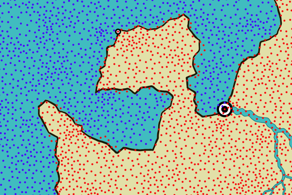
Here you can see how the centers of some land locations are actually outside of the land polygon.  But crucially, none of the sea locations are inside the polygon.

However, this doesn't fix the river problem in all cases.  The river needs to be drawn past the edge of the land, so that it is clipped to the land polygon and the mouth of the river aligns with the coast.  To force the river to be drawn past the coast, I identify all the sea locations that are immediate neighbors to land locations -- I call these “coastal" locations -- and then I make sure the river extends out to a coastal region.  The result is that the river crosses the coastline and is clipped properly.  In this illustration, I've marked the coastal locations with green:
You can see the river is now clipped correctly.

With that in place, I can now experiment with making the coastline more interesting.  Here's how the coastline changes if I add a sizable amount of jitter:
This doesn't do much beyond change the shape of the coastline a little.  That's because I'm using the same line segments and just moving the endpoints around a bit.  That doesn't add any detail.  If I break the original line segments up into pieces and jitter the pieces:
The jitter adds some complexity to the coastline and oddly enough also softens it.  This is because breaking the line segments down into smaller pieces and jittering the pieces effectively creates curves.  This is a somewhat more interesting coastline, but doesn't produce the kind of fractal look I'm seeking.

Jitter moves each point randomly and independently.  It might be better to use noise to move the points around, so that nearby points move roughly together.  Octaves of noise might also help create fractal detail, as it does when creating a fractal landscape.
This certainly has a greater level of detail, but it reminds me more of a Dr. Seuss illustration than a real coastline.  There are also numerous artifacts where perturbing the coast has caused it to cross itself.

If I want a fractal coastline, perhaps I should try using a fractal generator.  There are a few articles on using fractals to generate coastlines, but nothing I can really use out of the box, so I'll have to implement it myself.

One of the simplest fractals is the Koch curve, which you've probably seen before.  The basic idea is to divide a line segment into three parts and then add a triangle to the center part.  Doing this repeatedly creates an increasingly complex shape:
Of course, this produces a perfectly regular structure, which is not what I want for a coastline, but that can probably be fixed.  So let me implement a Koch curve and apply it to a simple line segment like a bit of flat coastline:
Let's see how this looks if I vary how the line segment is split into three pieces, so that the pieces can be different sizes:
Varying the height of the bumps changes the character of the line.  With low values, the triangle becomes lower and more smooth:
Which starts to look like a coastline.  With high values a problem becomes apparent:
The line starts to overlap on itself and self-intersect.  It makes an interesting pattern but would be a problem in a coastline.

Using a negative value for the height inverts the line:
Which viewed this way looks like the silhouette of a cartoon cloud.

For my purposes, one of the most useful settings is to mix negative and positive height values, so that the fractal sometimes goes one direction and sometimes the other:
And with a lower height value:
Even this relatively unsophisticated approach looks pretty good.

Before going on, let me fix the problems that arise when the coastline self-intersects.  Trying to prevent this from happening is pretty difficult, but fixing it afterwards is straightforward.  Beginning at one end of the line, I scan ahead a segment at a time.  If the current segment intersects with a later segment in the line, I keep the intersection point and clip out everything else.

Even large height values are now okay:
Although you can see there are many spots where the line comes very close to touching itself.

At the high values, the triangle nature of the fractal is fairly evident but that can be eliminated by going deeper into the fractal (and using a thinner line to show the detail):
Before I go any further, let me try this on the coastline and see how it looks:
Well, that's disappointing.  Why did that happen?  The problem is that I'm fractalizing each segment of the coast line.  But those segments are not very long -- basically just long enough to get one triangle stuck into them -- which turns the coastline into a series of spikes/anti-spikes.  As a quick first attempt to improve this, I can use line simplification to create longer line segments on the coast:
Still rough and not quite where I want it to be, but showing enough promise to continue experimenting.

To return to the original problem of fractalizing a line, so far I've been using the Koch curve, where a part of the line is recursively replaced with a triangle (or 2/3 of a triangle).  I can change that to be a three-sided figure pretty easily:
Not unsurprisingly, this gives a more rounded fractal.  It doesn't look too bad on the map:
Increasing the number of sides quickly breaks down, because the resulting segments are too small for the next level of recursion.  The Koch triangle produces four segments of length/4.  The three-sided figure produces five segments of length/5, and so on.  With higher numbers of sides the segments quickly too small to be fractalized themselves.

Choosing a random number of sides from 2 to 4 so that each fractal varies makes the character of the curve less predictable:
So far, every recursive level of fractalization uses the same ratios of sizes.  To change that, I can borrow the notion of persistence from noise generation. With persistence, as the scale of the noise grows finer and finer, the amplitude of the noise is reduced.  If I apply that same idea here, I get a fractal line that gets smoother as the scale gets smaller:
If you compare this line to the previous one, you can see that there is similar large scale changes, but at the finer scale the line is smoother.

I can also reverse the persistence, so that at a large scale the line doesn't change as much, but there is added detail at a lower level:
Here the line is closer to the original straight line, but with strong fine detail.  This seems like it might be useful for coastlines, so that the fractalization doesn't wander too far from the original line, but still adds detail.

A limiting factor in my implementation so far is that the fractalization part only works on line segments, so when I apply it to the coastline I have to essentially throw out the existing detail and just treat that section of coastline as a straight line.  If I set the fractalization low, it's obvious that the coastline is being reduced to low resolution segments:
I call this the Picasso map.

So how can I avoid turning everything into straight lines?  In the Koch curve, the fractalization is caused by adding (two sides of) a triangle to a straight line.  I need a way to add a triangle to an arbitrary polyline.

You can think of adding the triangle to the straight line as offsetting a point in the middle of the line perpendicular to the line:
So if I want to do this to an arbitrary polyline, I need to offset perpendicular to the polyline.  In the case of a polyline, I don't have just a single line for the whole offset area, so I need to be able to offset by the perpendicular all along the polyline -- the perpendicular will keep changing.  I also need to know how far to offset along the perpendicular at any point:
So this triangle offset can be looked at as a pattern of offsets to the perpendicular by different amounts.  I'll turn the triangle offset into a pattern for the fractalization that tells me how far to offset given how far along the line I'm at -- then when I want to offset a point that is (say) 37% along the length of an arbitrary polyline I can look at a point that is 37% along the length of my fractalization pattern, find the Y value at that point, and then use that to control how far I offset the point in my polyline.

So what does it look like to apply this to a polyline rather than a line segment?  Here's a curved polyline:
And here's the same polyline after adding a triangle to it:
As you might expect, it is taller and more pointed.  That's perhaps not too interesting, but here's what it looks like if the fractalization is recursively applied (and allowed to randomly switch between negative and positive):
Since I didn't have to turn the line into a straight line, it has retained much of it's original shape.  So now I can apply fractalization to an arbitrary polyline.  Here's an example of this applied to a coastline:
The red line shows the original coastline before fractalization was applied.  You can see that unlike the Picasso Map, the original coastline did not need to be reduced to long straight lines before fractalization.   You can also see that the fractalization has made significant changes in the coastline -- eliminating big sections of land in some areas and adding some in other areas.

Now that fractalization of arbitrary coastlines is working, I want to add the capability to vary the roughness of the fractalization across the map, so that I can have smooth coastlines in some places and rough coastlines in other places.  This is evident in many real world places.  A good example is Ireland, which has a rough Western coast and a smooth Eastern coast:
Ireland's Western coast is probably rougher because it faces into the North Atlantic.  I could link this effect to ocean currents or something similar on my maps, but for a first approximation I'll just use a noise function to smoothly control the roughness of the coastline.  This view shows the original coastline in red and then the “fractalized" coastline in black underneath:
In this example, you can see that the fractalized shore follows the original coastline closely around 9 o'clock on the island, but up around 1 o'clock the shore is much rougher and deviates from the original shore quite a bit.
Here's what the fractalized coasts look like on a map:
This isn't quite the look I'm aiming for, so I'm probably going to revisit this with a different approach, but it's not entirely bad.  I like very much that the coast is smooth in some places and rough in others; that's a feature I will try to maintain.

Monday, December 10, 2018

Hand-drawn Lines Revisited

I have written previously about how Dragons Abound creates lines that look “hand-drawn."  This turns a straight, obviously computer-drawn line and adds jitter and small width changes to make it look like it might have been drawn by a person:
Despite using this, someone commented on my blog recently that my maps would look better if the coast lines were more hand-drawn.  That reinforced my own thoughts that the coastlines didn't look very “hand-drawn", so I decided to look into more to see if something was broken, or if there was something I could do better to give a hand-drawn feel.

The short version is that I didn't find anything really wrong in the hand-drawn line code, but I also agreed with the commenter that the lines it was producing didn't look very hand-drawn.  For example, here's a normal (magnified) section of coastline:
The coastline is a smooth, natural-looking line which varies a bit in width but doesn't have any of the jitter we associate with hand-drawn lines.

The primary source of the hand-drawn feel is jitter along the line.  Here's what that coastline looks like with some jitter added:
Two things that you might notice.  First, the coast line now strays a bit from the land in places.  This is a good indication that the line is being jittered because the random offsets to the line mean it sometimes no longer aligns with the land-sea boundary.  Second, the coastline now seems much more angular and composed of line segments instead of smooth curves.  Instead of getting a “jittery" version of the curved coastline in the first example, I got something else entirely.  So what happened?

You may recall that SVG is a vector format.  Curved lines in SVG are drawn by smoothly connecting the points on the line with Bezier curves.  In the first case above, the smoothly curving coastline is created by drawing Bezier curves between the points of the coastline.  (This happens via D3, which provides some helper functions to make this easy.)  For example, if I had a coastline with three points, D3/SVG would generate a Bezier curve to connect them and it would be drawn like this:
Now suppose I want to “hand-draw" this same coastline.  To do this, I want to make the line jitter back and forth a bit along its length.  So I can't use an SVG Bezier curve.  I need to break the line up into a bunch of smaller chunks and then add a bit of jitter to each new point.  That gives me this:
Oops.  How did that happen?  Recall that the coast line is really just those three blue points forming a triangle.  When I connect those three points with a Bezier curve, I get the smooth curve above.  When I interpolate the line between each of those points, I get straight line segments.  Those points are still drawn with curves (as above) but it is now constrained much more closely to the triangle shape.

The basic problem here is that the coastline is defined as line segments but drawn by connecting the points with smooth curves using SVG Bezier curves.  To make it look more hand-drawn, I want to break up and jitter the coastline as it is drawn -- that is, I want to jitter along the path that SVG creates for the Bezier curves.  How can I do that?  Well, one solution would be to throw out any use of SVG Bezier curves and calculate all curves myself -- essentially re-implementing SVG curves.  (That's actually quite doable, since for other purposes I already have routines that implement Bezier curves.)  Alternatively, I can continue to draw using SVG, but capture the line before it gets to the screen so I can interpolate and jitter it.  This has the advantage that I don't have to re-implement all of SVG's curve drawing capabilities!

The method for capturing the line as it is drawn is not immediately obvious, but is not difficult.  The key is that the D3 functions that draw the curves can be fed an optional “context" object that implements the CanvasPathInterface and will use that interface for drawing rather than using the screen as they normally would.  To capture the curve as drawn on the screen, I can create a custom context to interpolate the moves, lines and Bezier curves into a sequence of points.  Then I can jitter that series of points and draw it as a polyline.

It turns out that the D3js curves use only lines and cubic Bezier curves, and since I already have functions to interpolate those, implementing the context is pretty straightforward.  As a test I feed it the three points from above and see if it can interpolate the original curve:
Looks like it works.  (The points are not actually equally spaced here -- the math to do that is too complicated to be worth the effort.)

Now I can “hand draw" these points:
That looks pretty good.  Now I'm essentially jittering the curve as it was drawn on the screen.

The bad news is that if I use this to draw coastlines they look ... just about the same:
Again, you can see some spots where the land sticks out from behind the coast line, indicating that the jittering is actually happening.  So why doesn't it look hand-drawn?

There are two reasons.  First and most importantly, you don't perceive jitter very well on an irregular line.  Which makes sense -- if a line is close to being a regular curve, then the little imperfections are obvious.  If a line is irregular, you can't tell whether a little bump is jitter or intentional -- it's the fact that you know how a perfect line should look that allows you to see the imperfections!  Second, the use of curves to connect the coast points tends to smooth out the jitter.  (Although drawing with straight line segments doesn't make the jitter much more obvious, and looks less fluid.)

The lesson here is that the hand-drawn look really only works for regular, predictable lines where the computer can do a perfect job and the human hand cannot.  In retrospect, this shouldn't be too surprising -- the inspiration for the hand-drawn lines approach comes from various efforts to Xkcd-ify plots, and plots are of course mostly made up of regular, predictable lines.

Well, you win some and lose some!  Not every new idea works out.  Although this improvement didn't work for coastlines, it does work in some other places, such as hand-drawing the frame around the map:
So what does make a coastline look more hand-drawn?  I reviewed my inspiration maps and it's hard to see any consistent differences between the coastlines on those maps and the ones produced by Dragons Abound.  (In terms of line quality, at any rate.)  One area where human-drawn maps differ is in the level of detail on the coastline, as in this comparison:
You can see here that on the human-drawn map the coastline has a lot more fine detail.  Many human-drawn maps have an almost fractal level of detail in the coastlines.  This is problematic for Dragons Abound for reasons I reviewed when creating barrier islands -- namely, that Dragons Abound creates coastlines by drawing around the edges of the Delauney land triangles.  The amount of detail there is limited by the size of the triangles.  And since the land is colored according to the same triangles, if I add detail to the drawn coastline, it will no longer match up with the land-sea border.

The solution is probably to get away from drawing the land based upon the underlying Delauney triangles and instead use the coastline paths to draw and fill the land.  This would be a significant change to how Dragons Abound works, but it will enable a number of features I'd like to have.  Not just fractal coastlines, but it would make it easier to draw coastlines with decorative edges, like this:
It would also enable small islands and very narrow barrier islands.  I'll have to give some consideration to how hard the change would be.  Stay tuned!

(Spoiler Alert:  Yeah, I went ahead and did it.  More next time.)

Monday, December 3, 2018

Barrier Islands

The recent news stories about Hurricane Florence often mentioned the Outer Banks, which are a series of barrier islands on the coast of North Carolina:
Barrier islands are flat or lumpy areas of sand that form by wave and tidal action parallel to the mainland coast.  That often occur in long chains that may go on for many tens of miles.  The barrier islands are often separated by small tidal inlets, and may form lagoons between the islands and the mainland.

According to Wikipedia, barrier islands are on as much as 15% of the coastland, so you might expect to see them on most fantasy maps, but they're pretty uncommon.  And due to the nature of noise, you almost never see them on procedurally-generated maps that rely on noise for making landscapes.

To understand why, consider a vanilla island map:
This is essentially a circle that has been perturbed with some low frequency noise added to break up the circle shape.   Now let me try to use noise to break up the coastline and form some coastal islands.  Here's the same island with some low frequency noise added:
This has add some bays and points.  The features are pretty big because I've used a low frequency noise that changes slowly.  However, the noise isn't strong enough to create islands.  Let me raise the strength a bit:
Now I've created some islands, but they're basically circular blobs, and not necessarily hugging the coast.  I can try adding high frequency noise:
This can give me very jagged coastlines and small islands along the coast, but nothing that really looks like a barrier island.

One reason noise doesn't work well for this is that noise is uncorrelated in x and y, so although noise overall isn't random, the shapes it produces are random:
Which is good for some things, but not good for producing a particular shape like an island alongside a coastline.

As with other cases where I've wanted to generate a particular shape or area, the solution is to create a mask in the required shape and then use noise within the mask.  (And I can also use noise to perturb the mask into a more natural shape.)  Barrier islands are essentially long thin areas that are offset from the coastline.  So let me work on creating that shape mask.

To start with, I'll identify a section of the coast where the barrier island will lie.  That's done by picking a random spot on the coastline and then a second spot further down, marked here by the red line in the upper right:
To start creating the barrier island, I could just take the straight line between those two points and project it out a little ways into the water.  That would give me a very straight and unnatural looking island, but I could perturb the shape to hide that.  The real problem is that the island wouldn't follow the coastline.  That would probably look okay along a mostly straight coast, but would look strange on a curving coast.  It will be better to replicate the coast line as the basic shape of the island.

To do that, I need to make a copy of the coastline and then project it out into the ocean, perpendicular to the coastline.  I already have a routine for calculating the perpendiculars (normals) to a polyline from way back when I implemented hand-drawn lines, and my coastlines always run the same direction, so this is fairly straightforward:
Or would seem to be straightforward.  Let's see what happens when I project the coastline a little further out (to create the other side of the island mask) on a less smooth piece of coastline:
Two of the projected line segments intersect each other and create a dreaded figure-8 in the polygon.  This is known as the parallel curve problem.  You can't just offset the coast some distance, you must also take care of problems that arise from acute inside and outside angles.

I looked for some Javascript code to handle this problem, but the only example I found (here) failed rather spectacularly on some easy examples.  So I wrote my own.  The basic approach is to offset each point by the normal, but then to check if the new point creates a line segment that intersects any of the existing line segments.  If it does, you cut off the loop and insert a new segment consisting of the intersecting point and the new point.  At least for the test cases I've tried, this works well enough for my purposes.

So now I'm able to generate simple (loop-free) masks for the islands:
These are a little too regular, so I will perturb the outlines:
It's okay if these outlines touch land at some points, because barrier islands often do that.

The next step is to fill in the land, but before I do that I want to make the islands longer and add some logic to avoid overlapping islands if I create multiple barrier islands on the same coastline.
Now let me try adding the land.  To do this, I raise the height of any land location (which are Delauney triangles) above sea level:
There are a couple of things to note here.  First, in the upper left there's a fairly successful barrier island.  However, it's not like the island neatly fills in the polygon.  Instead, a number of triangles of land have been “turned on" by having their centers within the polygon.  This adds quite a bit of randomness to the island's shape.  Second, you can see that the other two islands were close enough to the coast that they just merged with the coast.  Since I'm actually trying to create islands here, I don't want to that to happen too often, so I'll adjust the generation to use more water gap between the coastline and the island.  (Eventually Ill also added a specific test to prevent this from happening.)
One nice thing about the irregular triangles that comprise the land is that it naturally creates the kind of tidal gaps that are typical in a barrier island.  The bad thing is that it generally creates blobby islands that look like distorted pearls on a string.  They don't look much like barrier islands, and when you have many single triangles, it starts to look very unnatural.

If I increase the width of the islands, both effects go away, and I get more natural looking islands, but without tidal gaps:
But I'd still like to be able to generate really narrow islands.  Another approach is to (greatly) increase the number of world locations to improve the resolution:
This can achieve some impressively thin and detailed islands, but it greatly increases the time and memory to create the map.

With any of these methods, there's a good likelihood that some parts of the island will be very jagged:
This happens because the outline is hitting two sides (or sometimes all three sides) of the underlying Delauney triangles.  This is an inherent problem in using the Delauney triangulation in map generation -- and not one I see often discussed!  This doesn't show up as much on DA's coastlines because there's an intentional smoothing step to reduce this, but that smoothing step tends to eliminate narrow islands.  A potential solution is to make slightly wider islands and use the smoothing as well -- with some tuning this yields thinner islands without lots of triangle artifacts:
However, there's still a limit to how thin islands can be with this approach.  It also means you never get really fractal coastlines.

The smoothing algorithm sometimes causes the long barrier island to break up into smaller islands (as in the lower left islands above) but it's handy to have an option to force that to happen as well:
The only thing that remains is to name and label the islands.  The only slightly tricky aspect is that I don't really want to name every island in the barrier island chain.  In real barrier island chains, the individual islands often do get named, but that makes labeling a mess:

So when I create the barrier island, I make note of the entire arc and attach one label to that, even if the generation actually ends up breaking the arc into multiple islands:
“Banks" and “Bars" are appropriate for barrier islands, so they're options in the naming.

This example shows a potential problem with barrier islands:
Here the barrier island has been created inside a bay.  That doesn't make a lot of sense (and leads to label clashes besides).  To prevent that, I can use my bay-detecting logic to detect and then avoid these stretches of coastline.  This is probably not foolproof, but works well on this map: