Sunday, March 31, 2019

Map Borders (Part 8)

I still have some features I want to implement for map borders (Celtic knots!) but it's probably time I make some attempt at procedural generation of borders.  I've been dragging my feet for a couple of reasons.  Primarily I don't have any really great ideas about how to generate interesting borders -- and the notions I do have, have problems.

My intention has been to generate map borders using a generative grammar, similar to the approach I have taken for generating map names.  Part of the reason I developed MBDL was because the tools for generative grammars (like RiTa, which is what I use) are developed to generate text, so it's easier to use a tool to generate MBDL than to (say) generate the actual graphics.

However, there are some limitations to this approach.  Most of the generative tools (including RiTa) implement context-free grammars.  The context-free part of this means that the grammar rules always have a single symbol on the left-hand side, like these examples from Lost Coast names:
<coast> => coast | shore | banks <lost> => lost | forgotten | accursed <monster> => Zombie | Kobold | Orc <adj> => <lost> | <monster> <name> => The <adj> <coast>
Context-free grammars are pretty versatile, but there are some things they just cannot generate because of the limitation on the left-hand side.  One of those limitations pops up when you want to generate matching (or symmetrical) output.  Suppose you wanted to write a grammar that created a border with matching lines around an interior pattern.  You could write something like this:
<output> => <lines1> | <lines2> | <lines3> <lines1> => 'L' <other> 'L' <lines2> => 'LL' <other> 'LL' <lines3> => 'LLL' <other> 'LLL' <other> => ...(etc)...
This would generate one, two or three matching lines around <other>.  Now suppose I want to extend this to be any number of lines.  The obvious way to do this is to write a rule to generate a random number of lines:
<output> => <lines> <other> <lines> <lines> => 'L' | 'L' <lines> <other> => ...(etc)...
Here the <lines> rule generates a single line, or a single line followed by a <lines>.  This will generate some random number of lines.  But the two uses of <lines> in the <output> rule won't necessarily produce the same random number of lines!  To do that, the second use of the <lines> rule would have to know about something that happened in another place in the grammar -- it needs “context" which it cannot have in a context-free grammar.

Because of this limitation, you can only implement symmetrical output within a single rule.  This is a pretty crippling limitation for generating map borders, because as we have seen in many examples, symmetry is an important part of almost every map border.

This sort of limitation pops up more frequently than you might imagine, so most generative grammar tools have built in at least some additional capabilities to get around these limitations.  RiTA, for example, includes the capability to execute arbitrary Javascript within the grammar.  However, at some point the workarounds become so complex and kludgy that it becomes hard to maintain and eliminates most of the advantage of using a context-free grammar in the first place.  The more I thought about what I wanted to do for map borders the less I liked the idea of kludging a fix using embedded Javascript, etc.

Eventually I realized that in this case I had another option because I'm also defining MBDL.  While it might be impossible to implement symmetry in a context-free grammar, I could implement symmetry within MBDL itself.  It sounds counter-intuitive, but I can add symmetry to MBDL and still be able to parse it using a context-free grammar, and also be able to generate it using a context-free grammar!

To add symmetry to MBDL I need two features.  First I need to be able to mark a sequence of map elements, and then I need another marker to show where to (symmetrically) re-create the marked elements.  I need a pair of symbols for this, and I'm starting to run out of handy symbols in MBDL, so I'm going to (re-)use parentheses for marking a sequence of elements.  I'll use the dollar sign to show where to recall the original sequence.  So for example:
(L(1,"black") VS(3) L(1, "red") VS(3) L(1, "blue") VS(2)) L(3,"gold") $
This says to draw black, red, and blue lines, then a gold line, then repeat the same black, red and blue lines.

A couple of notes about symmetry.  First, I don't really want to reproduce the saved sequence, I want to reverse it and then reproduce it.  I want it to be symmetrical around the middle of the pattern.  In the above example, the black lines should be on the outside of the border, so I need to flip the saved sequence before generating it again.  Second, I will allow saving multiple sequences.  In this case, the last sequence saved will be the first one reproduced.  Again, this will maintain the mirror symmetry for the border.

Here is an example, using this border:
(L(1,"black") VS(3) L(1, "red") VS(3) L(1, "blue") VS(2)) L(3,"gold") $
Note that I can generate the same border with this MBDL:
(L(1,"black") VS(3)) (L(1, "red") VS(3)) (L(1, "blue") VS(2)) L(3,"gold") $ $ $
which uses three save/recall sequences.  The first recall brings back the last saved sequence, so this is the equivalent of doing it all in one save/recall.

With that implemented, I can start writing a generative grammar for MBDL.  I can certainly use this to generate a variety of borders similar to my example borders, but I'm not sure it will be able to create new and interesting borders.  At any rate, I don't have any better ideas at the moment, so I'll press on with this and see where it goes.

To start off with, I'll implement some rules to generate simple line borders:
<Color> => "black" <Width> => `Utils.rand(1, 3)` <Line> => L(<Width> <Color>) <VS> => VS(`Utils.rand(2, 5)`) <Border> => <Line> | <Line> <VS> <Line> | (<Line> <VS>) <Line> $ 
(Anything within backticks is executed as Javascript; in this case to generate random numbers.)  If you examine the rules, you'll see that a Line is black and has a width of 1-3.  A vertical space is width 2-5.  Finally, a Border is either a Line, two Lines separated by a vertical space, or three Lines with the outer two symmetrical.
I'm not sure I want to have offset corners decided as part of the border creation, but at least for the moment I can add that in as an option:
<LineBorder> => <Line> | <Line> <VS> <Line> | (<Line> <VS>) <Line> $ <Border> => <LineBorder> [3] | O(CLIP, SQOFFSET) <LineBorder> [1]
The numbers in brackets are weights.  In this case, it means that square corners will show up three times as often as offset corners.
In the reference maps there's a border version with a thin inner line and a thick outer line.
<Thick> => `Utils.rand(8, 12)` <ThickLine> => L(<Thick> <Color>) <Border> => <Line> | <Line> <VS> <Line> | (<Line> <VS>) <Line> $ | <Line> <VS> <ThickLine>
There's also a version with what look like narrow white lines one either side of a thick central line.
<Border> => <Line> | <Line> <VS> <Line> | (<Line> <VS>) <Line> $ | <Line> <VS> <ThickLine> ((<Line>) <VS> $ <VS>) <ThickLine> $
The next kind of border has overlapping lines like this:
Creating this is tricky -- it involves moving outward to draw the square offset lines and then back in to draw the regular lines.
<hothachar> => {O(SQOFFSET, 40) O(CLIP, SQOFFSET, 18, 40) VS(18) (<LineFilled>)} O(SQOFFSET, 0) $',
(“Hothachar" being the name of the map the inspired this border.)  It would be preferable to not hard-code the various offset distances, but that would require some fussing around with embedded Javascript.  I have a notion how to do this more cleanly, but it will require me to implement a new RiTa language feature.  (See below)


The last of the simple line borders from my reference maps is a colored border.  For now I'll just implement a few simple color choices.
<FillColor> => "gold" | "darkgreen" | "darkred" <ThickFilled> => <Line> <VS> (<Line>) L(<Thick>, <FillColor>) $
Which generates this:
If I need to generate two completely identical lines, I can use the “save" and “recall" feature of MBDL to do that.  But suppose that I want to generate two lines that have the same width, but different colors:
That turns out to be difficult to do.  When I draw the first line, I can randomly select a width for the line, but in a context-free grammar there's no way to remember that choice and reuse it later.  This is the same problem I had in implementing the “Hothachar" border above -- I didn't have any way to pick a random offset and then remember it for reuse later.

This is a pretty handy feature to have, so many tools implement some way to do this.  However, the tool I'm using, RiTa, doesn't happen to provide this feature, so I'm going to add it.  The implementation is pretty simple.  If the left side of a rule starts with a dollar sign, I'll treat it as a one-time rule:
$width => 18 | 19 | 20 <Line> => L($width, <Color>)
The first time a one-time rule is encountered, the rule fires as normal to create a value.  Any time after that, the one-time rule just reuses whatever value was generated the first time it was fired.  This is also the capability I need to avoid hard-coding values in the “Hothachar" rules above.

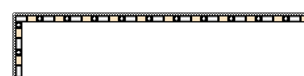
I can use this feature to pick a size for the boxes in a scale and keep all the boxes the same length:
With this feature implemented I have the flexibility to implement a number of additional border forms.  I'm not going to bother showing all the rules from this point; I'm sure you get the idea.

Up to this point I've done lines.  Now let me generate borders with patterns.  Patterns are sequences of repeating geometric shapes, and they provide much more complexity (and interest) than lines.

A simple pattern from one of my example maps has alternating bars and diamonds.  I can generalize that a bit and create patterns with different elements:
One variant is to use colored pattern elements

I used random color choices to generate these examples, but that's clearly not good.  For the moment, I'm going to use a black background for borders and I'll use the land and sea colors from the maps for accent colors.  There's probably more creative ways to handle color, but this will at least tie any color in the map border back to the map.

The example maps also have some borders where the elements are filled with gradients to create a faux 3D effect.  That can be added by using gradients to fill instead of colors:
At the moment I'm limited to some pre-defined gray-scale gradients, but in theory I could create and use color gradients as well.

A problem pops up here with offset corners:
When there's not enough room for even a single repeat of the pattern, things break.  I was fixing this by not drawing the pattern at all, but that leaves an empty corner that looks odd.  I think a better fix is to draw as much of the pattern as possible and then break off.  This puts a partial repeat into each of the legs of the offset corner, which is not ideal but usually looks better than leaving a blank area:
Maybe replacing the pattern with something like small dots would look better?  Something to think about.

Patterns can also have lines on either side to frame the pattern:

These edges can be dashed.
Dashed lines are actually made using a smaller pattern of boxes alternating with spaces.

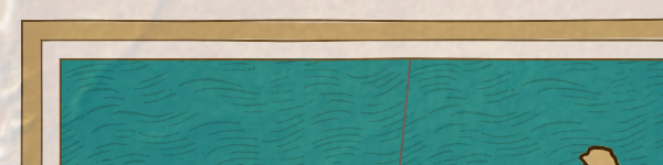
Dashed lines can also be used to make fancy neatlines:
And various combinations:

Another pattern variant is alternating small and large pattern elements, to get a separator effect.

A skinny bar also makes a good separator:

Another pattern variant is stacked pattern elements:

Currently I'm only stacking similar elements in a fairly simple way: the same shapes, with the “top" element being outlined in black and either white or a pattern color.

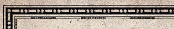
Another pattern feature is the “lace edge."  This is made by putting another pattern of touching circles under the main pattern:
If the border has an edge, the lace ends up between the pattern and the edge:
Here are some other lace variants:
 
There's a surprisingly good variety from intermixing a few different shapes with about ten rules.  I can also generate the lace on both sides of the central pattern.  I haven't decided if I like this or not, but implementing it drove out a two serious bugs in my MBDL interpreter, so I guess that was good:
The lace edges also work pretty well as the main patterns in a border:
As sometimes happens, I didn't have any good ideas when I started this phase of implementing map borders, but just plunging ahead and trying different things has produced some decent results.  More to come on borders, but let me end this post with an example map and border:
I really like the “lush tapestry" feel of some of these complex borders.  As always, you should be able to click through for a bigger image.

Monday, March 25, 2019

Map Borders (Part 7)

I'm still procrastinating on tackling the procedural generation aspect of this topic, so this time I'll look at actually using the new borders on a map and try to duplicate some of the more interesting borders from my reference maps.

One immediate challenge with using the new map borders is deciding the clipping area. When Dragons Abound creates a map using its current map borders and the border has an offset corner, Dragons Abound clips the map to the offset so that it doesn't appear in the offset area:
That isn't so easy to do with the new MBDL borders, because I want to preserve the option to have the border “inside" the map edge, as in this example:
I need a way to tell Dragons Abound where to clip the map, so I'll add a new MBDL option to define the clipping area:
O(CLIP, RECT, where)
O(CLIP, SQOFFSET, where, offset)
The first option tells Dragons Abound to clip the map to a rectangle.  Where defines the clipping area relative to the edge of the map, so a negative value for where clips insides the map edge.  The second option tells Dragons Abound to clip to a square offset corner.  Where has the same meaning, and offset defines the size of the offset corner.

With that fixed, I can now start testing some borders, starting with some simple neatlines:
Doubled:
Any of these borders can be given an offset corner, but I won't bother to show that for every border.
One of my reference maps has a doubled line border with a thick second border:
That's straightforward (although the reference map has a line texture that I can't currently do):
Another reference map has a border made up of five lines that register visually as two narrow white lines and one thick black line:
Here's the recreation (again, without the grunge filter from the reference map):
Because the lines on this border are closely spaced, rendering this with “hand-drawn" lines can create some spots where the lines waver into each other.

This next reference map mixes a square offset corner with no corner to create an overlapping effect:
This is not too difficult, but in this particular example the outer line is under the inner line.  Dragons Abound draws map borders from inside outward so the inside line would naturally be under the outside line.  To get it the other way around, I have to use a vertical space (VS) command to jump to the outside position, draw that line, then use a negative VS to jump back to the inside to draw that line.  In the reference map the frame overlays the map, but I'll clip to the offset:
This is a case where the offset used in clipping differences from the offset used in creating the border.  I need the clipping area to match the offset of the outer border but the dimensions of the inner border (if you see what I mean).

Note that Dragons Abound draws only sharp corners.  The reference map has rounded corners, which look nice.  I'm also “hard-coding" the colors in these examples; I might want to think about whether MBDL should support some color commands.

Another variant uses a wide colored line:
This is actually three lines (four counting the inner neatline):

I've already done a scale.  A variant is a three colored scale:
This fooled me initially.  It's a three color scale but it's actually a four element pattern, because there are white bars every other bar. 
I noted when creating this border that the “hand-drawn" embellishments don't work very well for scales:
Part of the reason “hand drawing" looks particularly bad for scales is that it make it obvious that Dragons Abound doesn't draw a scale the way a human artist would.  Dragons Abound draws each box individually.  A human artist would draw two long lines, and then break that up into boxes with short cross lines.  I'm not going to implement a special case for scales -- I'll just turn off the hand-drawn embellishments, or turn down the amount:
However, this does suggest that I might want to change this in the middle of a border (e.g., draw the scale without any embellishments, and then draw the rest of the border with embellishments).  So I might add another option to MBDL to cover that.

Another of my reference maps uses a border with a bars and diamond pattern.
This border also has a corner element, which I haven't tackled yet, but the rest of the border I can replicate:
This border also turned up a bug in the pattern layout logic, so I'm glad I replicated it!

Some of the reference borders have use a 3D effect on the border elements:
Currently Dragons Abound has some limited ability to replicate this effect.  The 3D effect on the circles is done using a gradient to make the color shade from light to dark.  SVG provides some gradient capabilities, so I can create a radial gradient and specify it as the “color" of the ellipse:
I have another example border with a similar effect for both ellipses and bars:
Recreated in Dragons Abound:
Here I've created a linear gradient to use as the “color" for the bars.  That looks okay on the top part of the map frame, but is wrong on the side!  For ellipses I only need one gradient, but for bars I will need different gradients on the top/bottom and sides of the map border.  (I'm not sure I can do diamonds with a gradient fill!)  To handle this, I'll extend the syntax of MBDL to allow a second fill color for bars that will be used on the sides of the map.
So now I can use the correct gradient on the sides of the map.  It's a bit of a pain to define the gradients and take care to use the right ones in the right place, so I may create a GRADIENT command for MBDL to automate some of that at some point.

Meanwhile, another kind of gradient shows up in this sample map:
Here a gradient has been used to make a line look three dimensional.  Here's a similar effect with colors:
Let me try that:
A couple of problems here.  First, just like with the bar elements, I need a different gradient on the sides than the top/bottom.  That's fixed by making the same change for lines that I did with bar elements:
Now the second problem is more apparent.  I got rid of clipping areas to create mitered corners, which made it possible for me to run patterns around more complicated shapes like offset corners, but it also means that line corners don't work for any non-solid fill color.

I need to cut off the lines on the diagonal in the corners, but I don't want to go back to the clipping areas -- then I'd just be back to square one with offset corners.  The other solution is to draw the line so that it has the proper diagonal end.

All of these border lines - even the big fat ones that look like fills - are drawn with the same line-drawing routine that does all lines in Dragons Abound.  Currently that routine has two options for line ends.  One is “butt" where the line goes straight across on the end.  (This is useful when drawing rectilinear lines, and is what is used in the picture above.)  The other is “round" where the end of the line forms a semicircle.  (This is useful when drawing lines that meet at random angles.)  Mitered ends are more complicated; there are four possibilities for horizontal lines and four possibilities for vertical lines.  (I won't try to implement the general case for lines at any angles, which involves splitting the difference of the angle at which the lines meet.)  On the other hand, you can easily figure out which angle to use from the orientation of the line. 
As with using clipping areas, there's sometimes a gap between the miters due to anti-aliasing.  In this case, I know that I'm only dealing with horizontal and vertical lines, so I can fudge the miters a pixel in the correct direction so that they are more likely to completely overlap.

That covers all the example borders I wanted to replicate.  That drove out a few problems, and it also gave me a better notion of the different possibilities for procedural generation.  So by next time, I'll surely be ready to tackle that ... I hope.